|

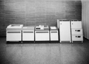
The NCR Century 101 is a powerful data processing system that can have a configuration to meet a wide range of business and scientific requirements. It performs well in batch processing applications where low-cost file capability is a major consideration. It also offers modest real-time capability, common trunk interfacing for a wide range of peripherals, low-cost simultaneity, and upward compatibility. This was a redesigned 615-100 platform that resulted in the 615-51, 615-101 and the 615-151 (actually it was an entry level 615-200). The logic design approach changed from discrete logic to a ROM (Read Only Memory) approach. The logic was on 7x8 cards instead of 4x4. batch processing applications where low-cost file capability is a major consideration. It also offers modest real-time capability, common trunk interfacing for a wide range of peripherals, low-cost simultaneity, and upward compatibility. This was a redesigned 615-100 platform that resulted in the 615-51, 615-101 and the 615-151 (actually it was an entry level 615-200). The logic design approach changed from discrete logic to a ROM (Read Only Memory) approach. The logic was on 7x8 cards instead of 4x4.
The modular concept of the central processing unit permits the user to expand his system without changing processors or software. The processor ' s memory can be expanded in increments of 8K bytes from 16K to 32K, then in 16K increments from 32K, to 48K, to 64K. I/O capabilities can be expanded from the basic 2-trunk configuration (1 low-speed trunk and 1 high-speed trunk) to a 4-trunk configuration (2 low-speed trunks and 2 high-speed trunks). If online data communication with remote terminals or other processing systems is required, communication capabilities can be added.
A wide range of NCR Century peripherals can be used with this processor. Printers with speeds from 300 lines per minute up to 2000 lpm are available. Freestanding disc units with transfer rates ranging from 312 KB to 500 KB and storage capacities of 4.9 megabytes to 48 megabytes per disc pack are available for use with the NCR Century 101.
Central Processing Unit
The central processing unit (CPU) is the heart of the NCR Century 101 System. A single cabinet houses the entire processor memory, contains all of the logic necessary for data manipulation and I/O control, and (3) contains the necessary logic and electronics for both the operator's console and the integrated COT (card or tape) reader. The auxiliary cabinet must be included if the system configuration contains an integrated printer or I/O Writer. This cabinet contains the power supply and logic for the printer and also houses the standard I/O Writer or the thermal I/O Writer if desired.
The CPU has a basic repertoire of 34 hardware commands. Three optional commands are also available (LOGIC, MULTIPLY, and DIVIDE). Hardware commands perform many of the functions normally performed by slower software routines in smaller systems, thereby providing greater processing efficiency. For example, the signed versions of the add and subtract commands enable the system to manipulate packed data without forcing the programmer to first unpack it and then repack it following manipulation; also, the test character commands enable the system
to compare two 8-bit characters and (depending upon the result) transfer control in the same operation.
The processor consists of four major sections: the memory section, the arithmetic logic unit, the I/O control section, and the operator's console.
Memory
The processor's memory, which is contained entirely within the processor's main cabinet, is binarily addressable by command or console entry. The basic storage unit is the byte, which consists of eight data bits and one parity bit. For faster command setup and addressing capabilities, memory is accessed two bytes at a time; however, data may be written into memory in either one- or two-byte increments. The time to access or store a byte of information in memory (memory cycle time) is 1.2 microseconds.
The processor logic provides four addressing modes: direct addressing (Mode 0), indirect addressing (Mode 1), indirect addressing (Mode 2), and incremental addressing (Mode 3). These four addressing modes provide the programmer with a very versatile method of memory access. He may specify an absolute address with Mode 0 addressing, use the address specified in another area of memory or another command by using Mode 1 or 2 addressing, and incrementally step through an area of memory using Mode 3 addressing.
Each addressing mode permits the use of index registers to create an effective memory address. There are 63 index registers in the processor's memory.
Registers 1 through 12 are reserved for software control; the remaining 51 may be used as work registers.
|

